One of the most challenging phases of database design is the fact that designers, programmers, and end-users tend to view data and its use in various forms. Unfortunately, unless all the database learners gain a common understanding that reflects how the enterprise operates but the design you may produce will fail to meet the users' requirements. To ensure that you get a precise understanding of the nature of the data and how the enterprise uses it, you need to have a universal model for interaction that is non-technical and free of ambiguities and easily readable to both technical as well as non-technical members. So the ER (Entity Relationship) Model was designed and developed and is represented by an ER diagram. In this chapter, you will learn about the ER diagram and its working.
What is Entity Relationship Diagram (ER-Diagram)?
ER-Diagram is a pictorial representation of data that describes how data is communicated and related to each other. Any object, such as entities, attributes of an entity, sets of relationship, and other attributes of relationship, can be characterized with the help of the ER diagram.
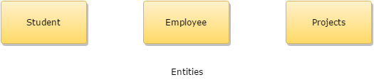
Entities: They are represented using the rectangle-shaped box. These rectangles are named with the entity set they represent.
ER modeling is a top-down structure to database design that begins with identifying the important data called entities and relationships in combination with the data that must be characterized in the model. Then database model designers can add more details such as the information they want to hold about the entities and relationships, which are the attributes and any constraints on the entities, relationships, and attributes. ER modeling is an important technique for any database designer to master and forms the basis of the methodology.
- Entity type: It is a group of objects with the same properties that are identified by the enterprise as having an independent existence. The basic concept of the ER model is the entity type that is used to represent a group of 'objects' in the 'real world' with the same properties. An entity type has an independent existence within a database.
- Entity occurrence: A uniquely identifiable object of an entity type.
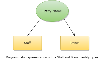
Diagrammatic Representation of Entity Types
Each entity type is shown as a rectangle labeled with the name of the entity, which is usually a singular noun.
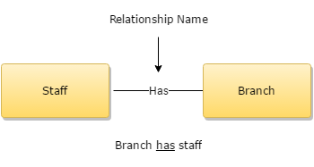
What is Relationship Type?
A relationship type is a set of associations between one or more participating entity types. Each relationship type is given a name that describes its function.
Here is a diagram showing how relationships are formed in a database.
What is a degree of Relationship?
The entities occupied in a particular relationship type are referred to as participants in that relationship. The number of participants involved in a relationship type is termed as the degree of that relationship.
In the above-figured example, "Branch has a staff", there is a relationship between two participating entities. A relationship of degree two is called binary degree (relationship).
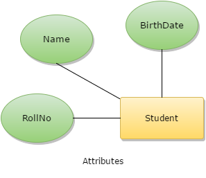
What are Attributes?
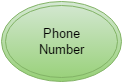
Attributes are the properties of entities that are represented using ellipse-shaped figures. Every elliptical figure represents one attribute and is directly connected to its entity (which is represented as a rectangle).
It is to be noted that multi-valued attributes are represented using double ellipse like this:
Relationships
A diamond-shaped box represents relationships. All the entities (rectangle-shaped) participating in a relationship get connected using a line.
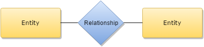
There are four types of relationships. These are:
- One-to-one: When only a single instance of an entity is associated with the relationship, it is termed as '1:1'.
- One-to-many: When more than one instance of an entity is related and linked with a relationship, it is termed as '1:N'.
- Many-to-one: When more than one instance of an entity is linked with the relationship, it is termed as 'N:1'.
- Many-to-many: When more than one instance of an entity on the left and more than one instance of an entity on the right can be linked with the relationship, then it is termed as N:N relationship.